Game Gear VA0 - 1
Console status
| Date | Power | Sound | RLB | Game operation | Screen |
|---|---|---|---|---|---|
| 2023/10/01 | ✔️ | ✔️ | ✔️ | ⚠️ | ❌ |
Console details
- Japanese Game Gear bought during my trip to Japan on August 2023
- It came with a broken japanese TV tuner
- The screen protector was already replaced but the console seemed unmodified (screws were tight and capacitors were the stock ones)
Add a picture of the console here. Show them the goods!
Specs
- Model Number: HGG-3210
- Serial Number: B0126683
- Main board: 837-7398-01 (Twin ASIC)
- Power board: 837-7399-01
- Audio board: 837-7400-01 (Initial release Japanese Game Gear with square-body surface mount caps similar to GG main boards)
Overview
Visual inspection
- Outside: The outside has visible scratches from usage but no cracks
- Main board: capacitor leaks are visible on its legs. Zone next to the fluorescent tube is damaged, it is just below the corroded battery spring so battery leak might have been the cause
Add picture of corroded zone of the main board.
- Power board: no visible leaks
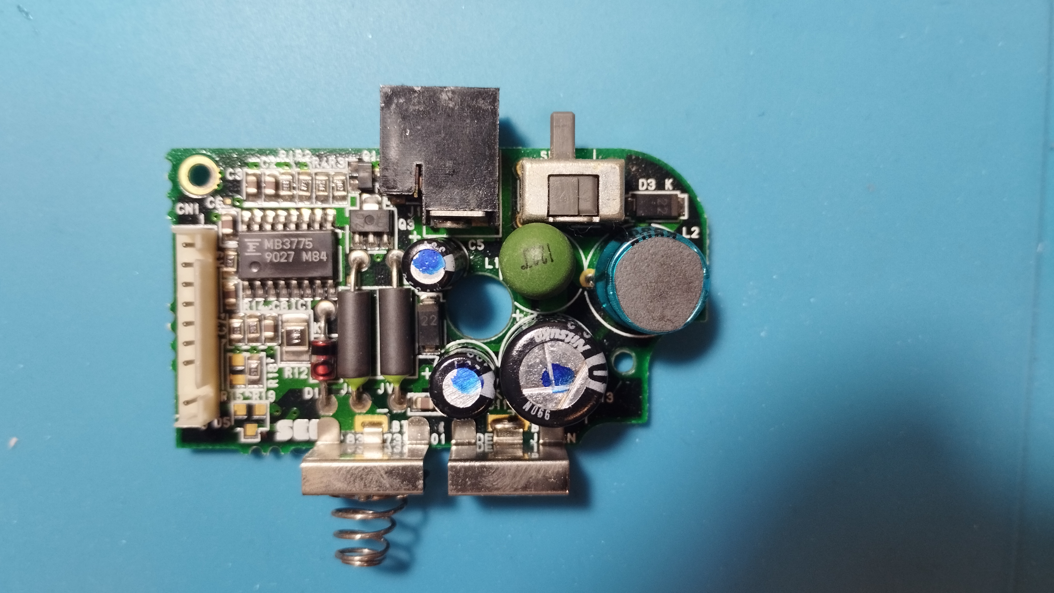
- Audio board: visible leaks in capacitors
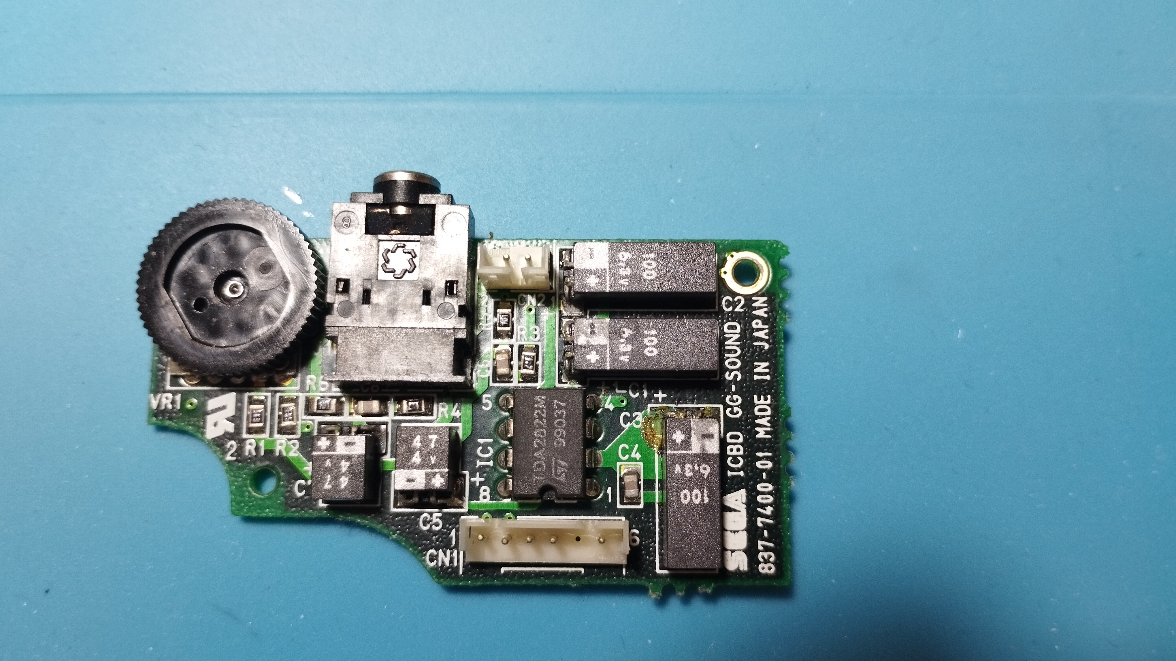
- Battery contacts: some rust in the battery compartment as well as in some springs, but nothing serious.
First boot
- Power LED turns on a few seconds and then it turns off
- The screen doesn’t turn on and there’s no sound either
Maintenance
2023/10/01: Recap
Following Retrosix’s wiki, the capacitors are replaced like this:
Power board
- Capacitors are replaced with new electrolytic ones with the same rating
- The only exception is the 820uF/6.3V one that has been replaced with a solid electrolytic capacitor of the same rating (does it make any difference compared to the standard electrolytic ones?)
- According to the data sheet, solid electrolytic capacitors have a low ESR and high ripple current
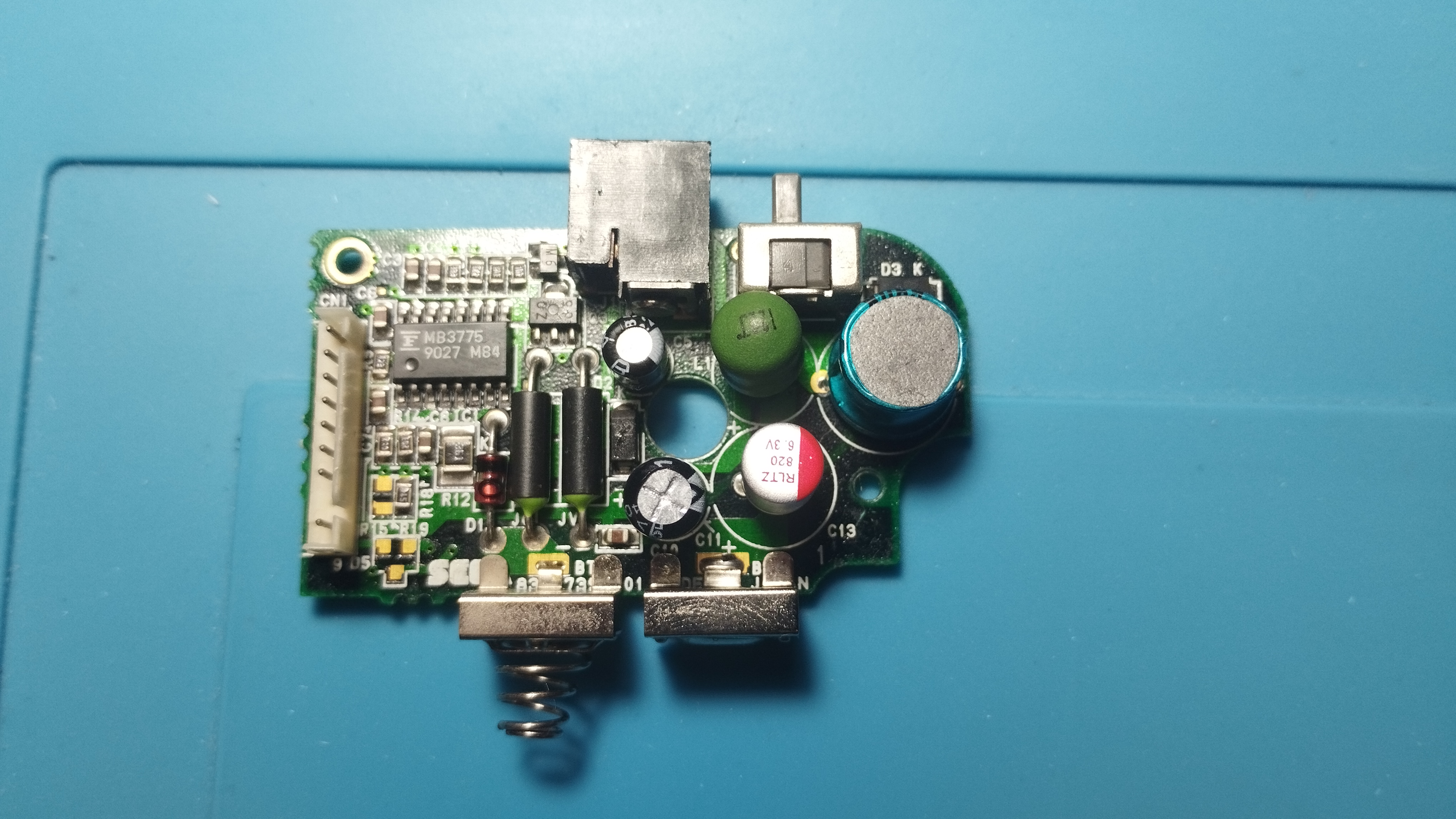
Removing some capacitors proved to be quite challenging, even with an electrical desoldering pump. The trick to keep the vias intact is to reapply new solder several times to mix old solder with new one. Flux is indispensable to help transfer heat on already old and dry solder as well!
If a leg is stubbornly stuck, use some desoldering wick with new solder and a lot of flux to remove the excess inside the via by capilarity. Rinse and repeat until the leg is free!
Audio board
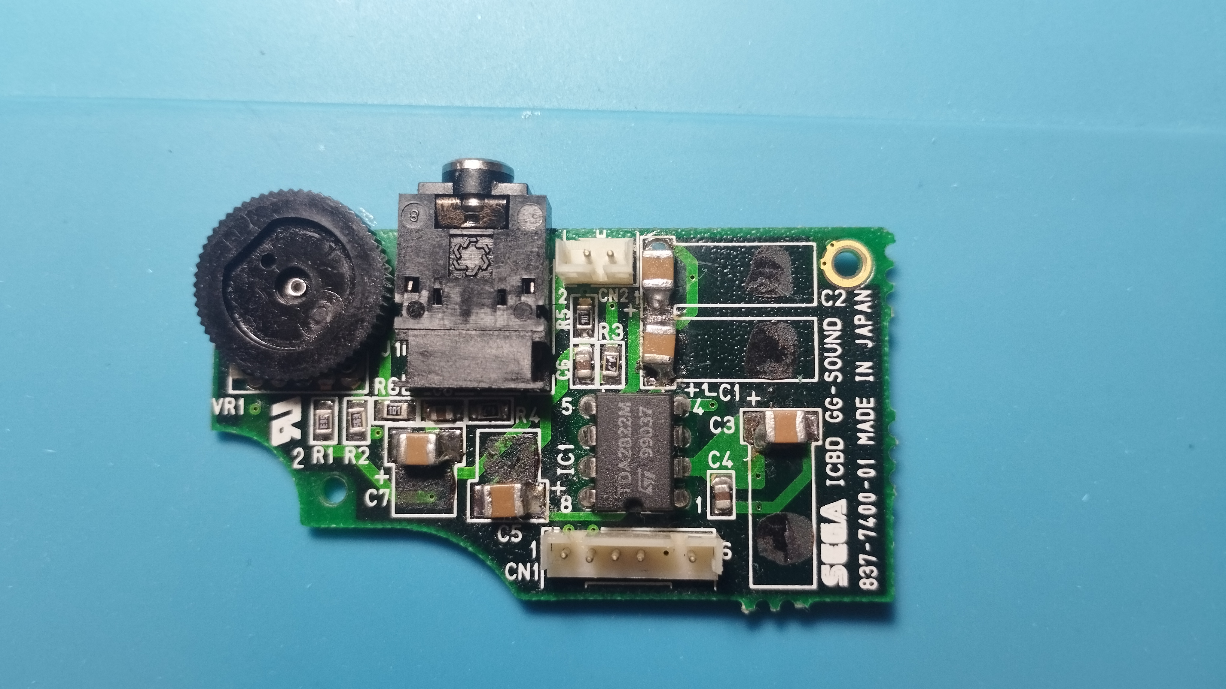
- All capacitors are replaced with 100uF/10V ceramic capacitors
Main board
- All original capacitors rated lower than 1uF are replaced with 1uF/50V ceramic capacitors
- All original capacitors rated lower between 1uF and 10uF are replaced with 10uF/50V ceramic capacitors
- All original capacitors rated higher than 10uF are replaced with 100uF/10V ceramic capacitors
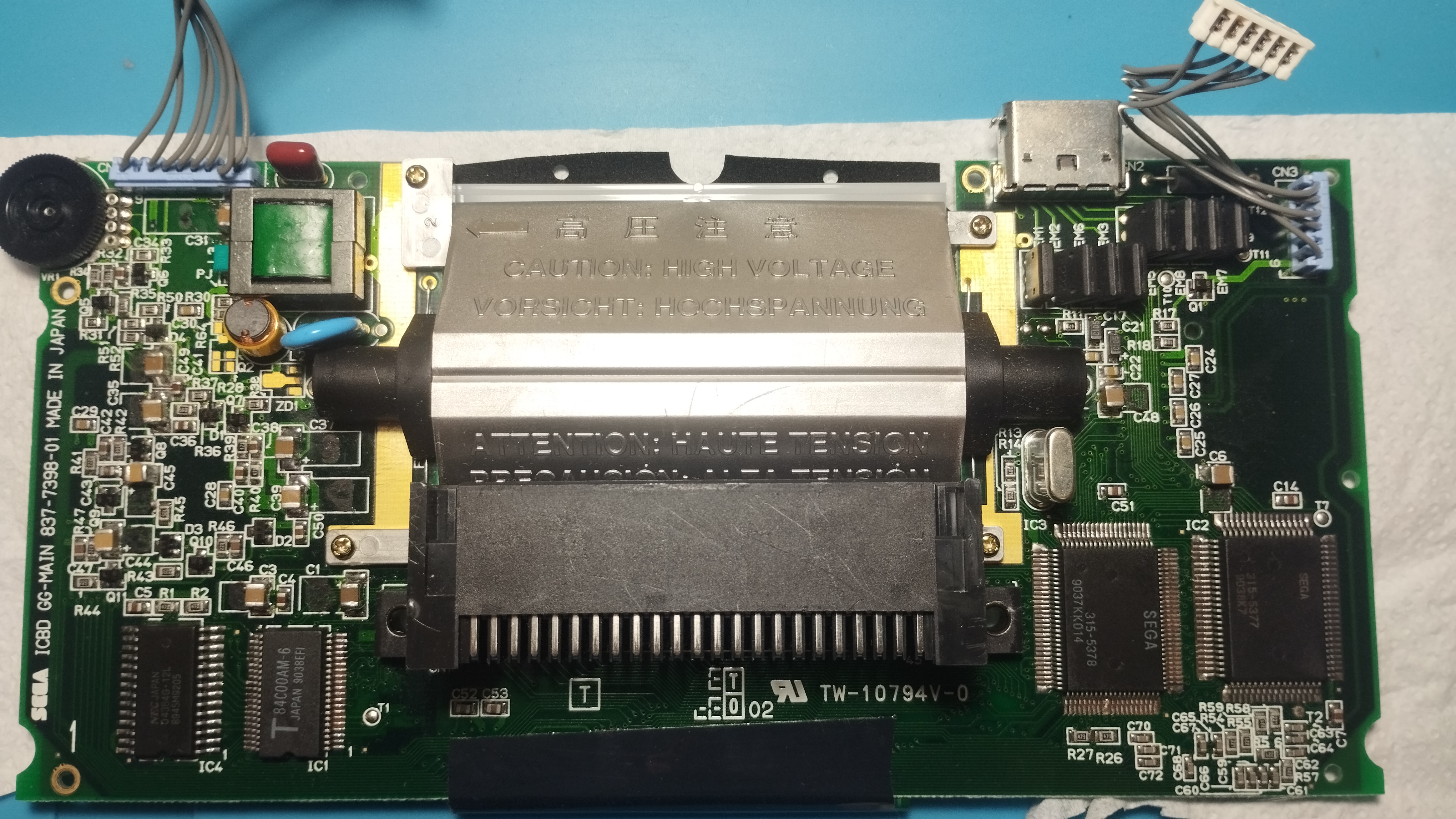
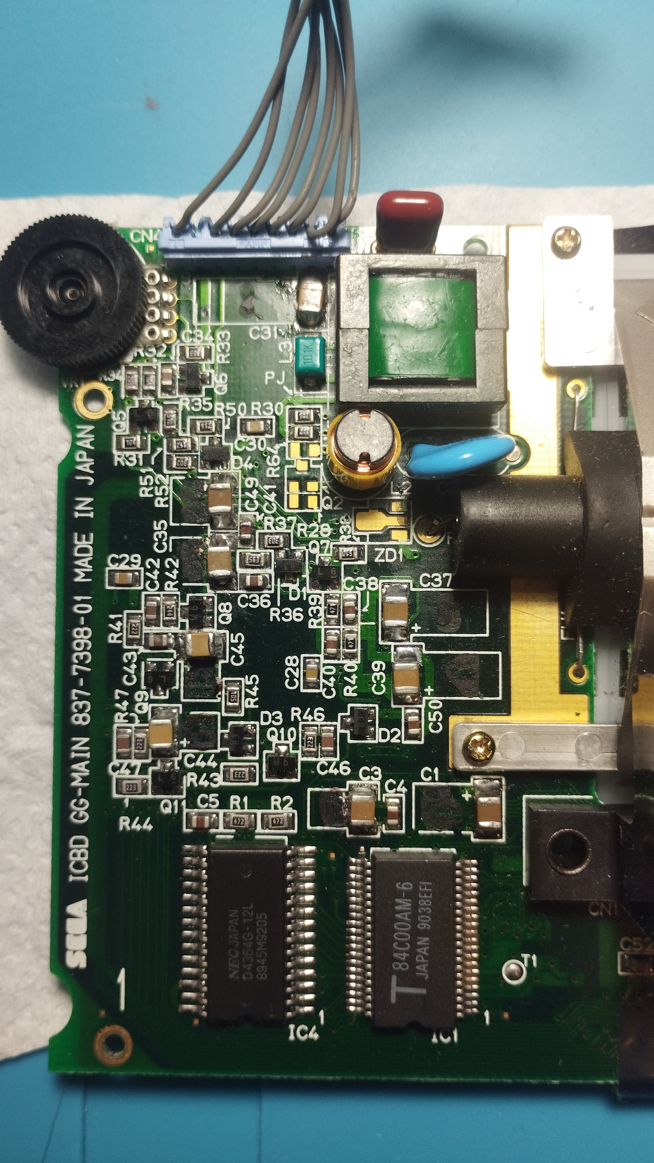
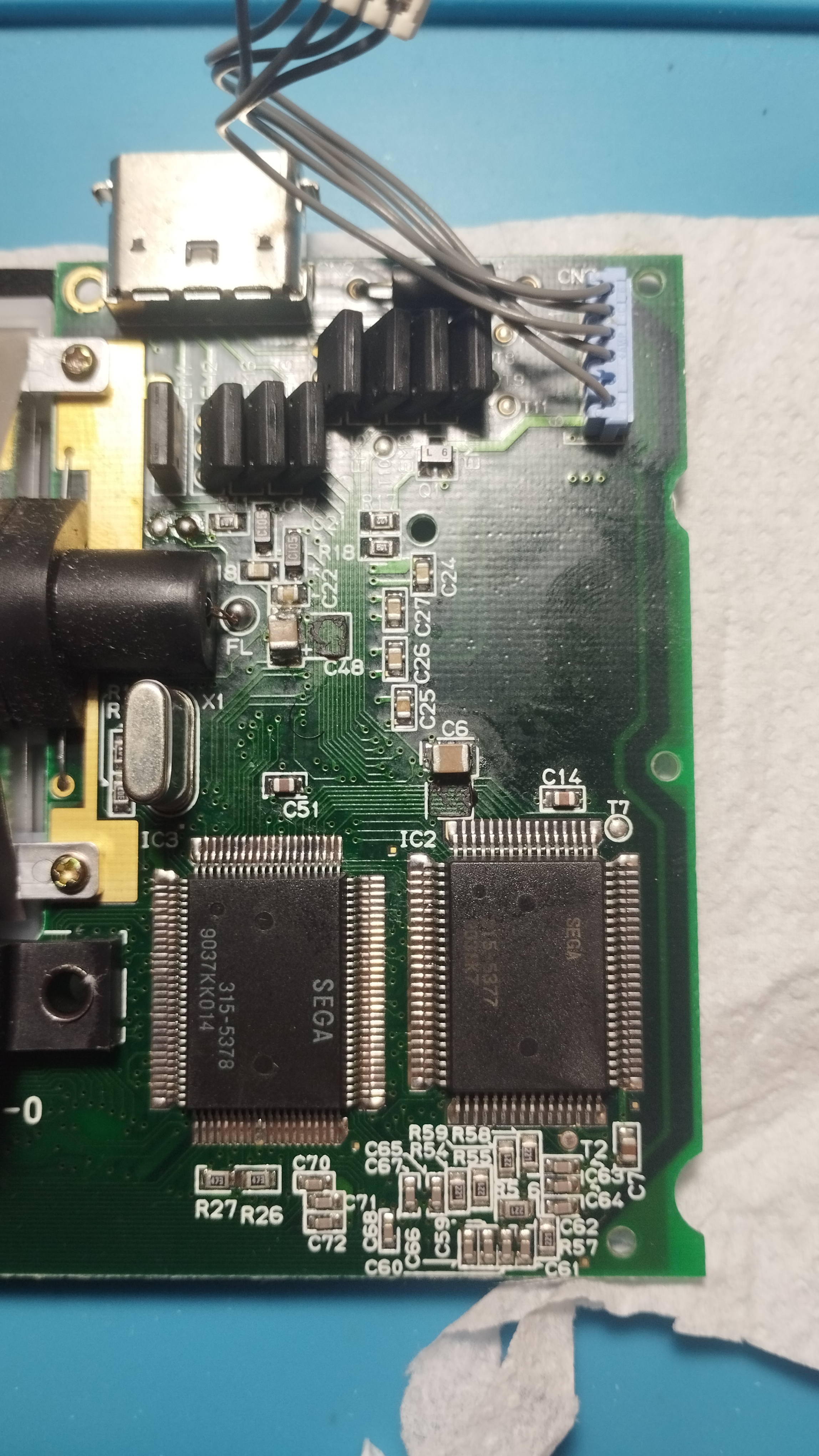
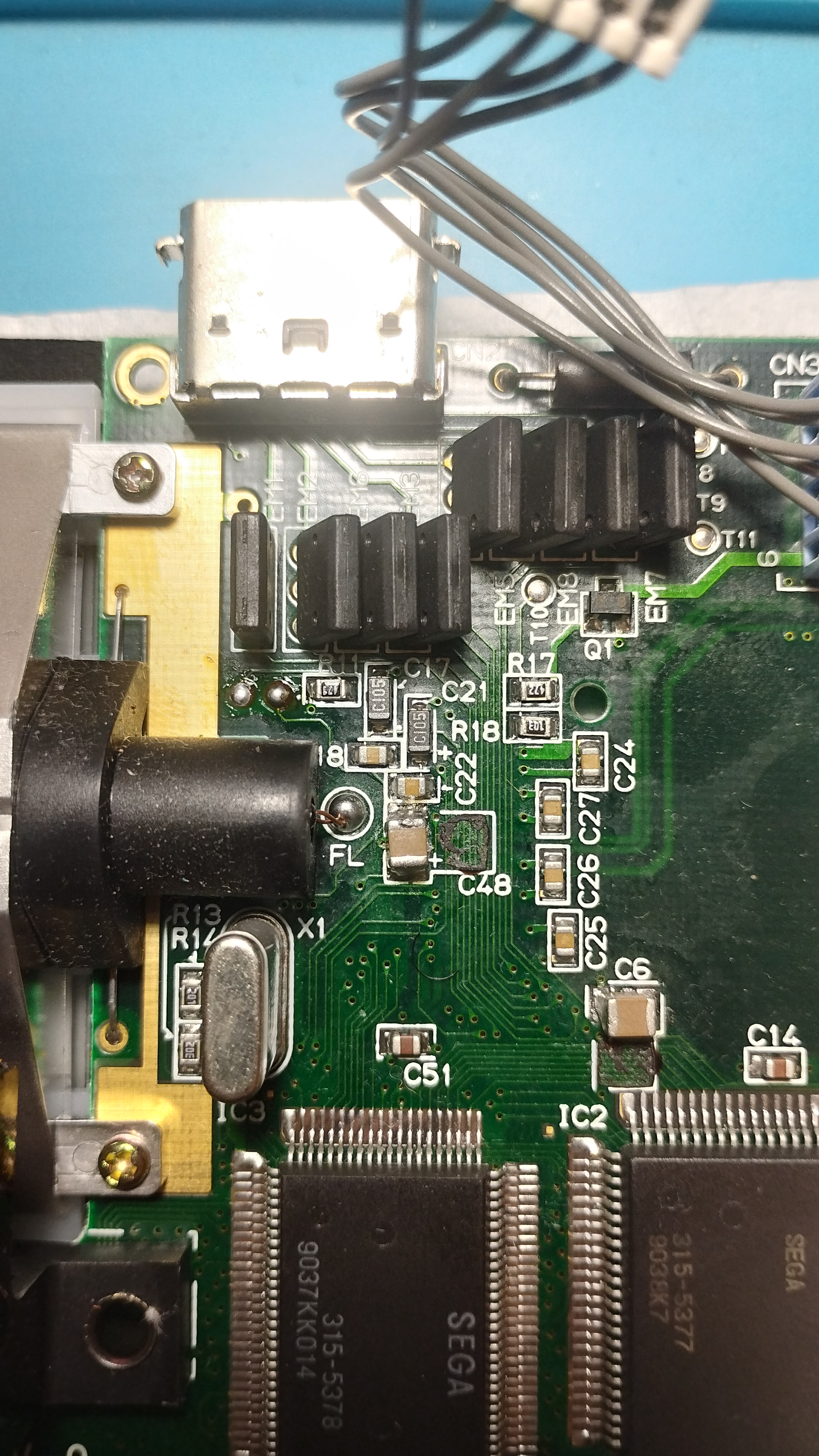
Some capacitor pads presented a huge amount of corrosion, making it a little bit difficult to reheat and clean them. Before applying any heat to the corroded pads, I applied some vinegar in order to neutralize as much as possible the leaked acids. Using soldering paste proved to be quite useful in areas where the soldering iron could potentially melt plastic connectors, as its low-temp melting point made for quicker joins.
2023/10/01
State on stable boot
- Console enters the Red Light Boot state, required for further troubleshooting and repairs
- All voltage levels are within the expected ranges
- Audio board also works, both the speaker output and the output jack
- LCD screen doesn’t turn on, neither the fluorescent tube
- I haven’t checked if there’s really no image on the LCD, pending to use some kind of light as replacement of the tube just to be sure
- There’s visible smoke and smell around transformer T1, L2 and C33
Continuity checks
- Fluorescent tube fuses are OK
- No continuity between cartridge pin 1 and the +34V rail
If everything else is fine, this console could be a good candidate for a screen replacement
Additional issues detected
- It seems that the zone where the voltage dividers are (full resistor network as RetroSix calls it) gets quite hot after a few seconds with the power on
2023/10/08
34V rail
- Repaired full rail. Now cartridge pin 1 receives 34V, but no improvements overall.
Next steps
T1 voltages
- Check T1 voltages, see if it is faulty
L2 inductor
- Check L2 inductor status
C33 capacitor
- Check if C33 capacitor is faulty